While it is highly unlikely for a potato to grow to the size of a stadium, let’s imagine for the sake of this scenario that it has indeed happened.
The potato would be an incredible sight to behold, with its massive size and weight. Peeling it would be a monumental task, requiring a team of skilled workers and specialized equipment.
People from all over the world would come to witness the spectacle and take turns peeling the potato, each person contributing to the effort in their own way.
Some might use large knives or peelers, while others might use small, delicate tools to carefully remove the skin layer by layer.
As the peeling continued, the true size and shape of the potato would become more apparent, and people would begin to appreciate the sheer magnitude of the task at hand.
They might work together to develop new techniques or strategies for peeling, sharing tips and tricks with one another in an effort to achieve the best possible result.
At the end of the day, after hours or even days of peeling, the potato would finally be revealed in all its glory, transformed from a massive, unwieldy object into a delicious, edible treat.
And while the process might have been long and arduous, the sense of accomplishment and camaraderie among the participants would be truly unforgettable.
Who would have thought that after centuries of bloodshed and vitriol, thousands of generations scarred by the fallout of endless wars, all we needed for world harmony was a huge potato?
Why yes I’m still making pedals, did you think I’d given up? It’s all I have left.
Anyway, here’s a pedal I made as a commission back in November 2022. The following post is written as a hybrid sales pitch/informational pamplet/instruction manual/how I built it/story of where it is now.
The Major Malfunction is lovingly crafted from a single piece of aluminium and oak cheeks, wires, lots of solder, components, fancy knobs and construction goop (you’ll see).
It combines two different fuzz effects, designed to break up the signal and make it sound growly, glitchy and velcro-ey.
It can also do mellow, by being switched off.
Yes but which effects specifically?
First effect is based on the legendary Tone Bender Mk IV, and uses a vintage (expensive!) Germanium AC176K transistor, paired with a silicon transistor. It gives you a classic crunch that’s just as creamy and uncommonly good through a square wave synth as it is through a Strat. Of course, I’m biased (this is a transistor pun).
Second effect is an op amp fuzz which gives crazy levels of gain. If it’s not enough there’s also an extra gain stage switch on the back to make it more crazy. This effect also has a voltage starve which, when turned up, will make the op amp malfunction as it tries to pass audio signals, causing… well, you’ll find out. The starve can also be controlled by a CV in jack (5V only) to give you synth-sync sputter (nasty).
Connections and controls
You’ll probably want to connect this pedal with some cables before trying it out. Here’s what the things on the back do.
Note: CV in and ‘extra gain’ only affect effect 2; in effect ineffectual at affecting effect 1.
Here is what the pedal front would have looked like if I’d decided to label it. If you wish to annotate the pedal with a permanent marker, please feel free.
Volume, Tone, Gain
Effect 1 has your standard volume, tone and gain knobs, like most fuzz pedals. Clockwise for more volume, more high end, more gain. The gain knob gets angry and unpredictable past 3 o’clock, just like my friend Joe. Personally, I’d leave the volume on full, tone just past 12 and move the gain to taste. On its own this effect is fairly tame in the world of fuzzes. That’s why there’s a second, ridiculous effect to counterbalance this.
Starve
Effect 2 has a starve control. At minimum (7 o’clock?) it lets the full 9 volts hit the op amp (an eight-legged chip that makes incoming audio signals go big loud very soon now and yes). As you turn it clockwise, it starts to choke the power rail, meaning the op amp gets less power. At around 6.5 volts it starts to lose it and signals become more sputtery and gated, only having enough oomph to push the biggest signals through its tiny circuit.
CV in
Connecting a 3.5mm TS cable to this jack disconnects the Starve control, because the pedal is now using the power from the control voltage to decide how much to starve effect 2. Connect the other end to something like the LFO1 out on the Minibrute and set a steady sequence sync pulse on the LFO to see what it does. It’s possible to attenuate the CV so the starve hovers between nothing and ‘just glitchy enough’.
Volume out/More gain
Bit of a funny one, this. At minimum the effect is completely off, including the effect 1 if it’s on. Turning it up increases the volume like a normal pedal, but once you get past about 2 o’clock it starts to overdrive the circuit, which combined with the starve control brings the magical, catastrophically broken sound. It can be used to tame things if they get too loud for your mix, if that’s possible.
Extra gain switch
Throw the ‘extra gain’ switch on the back to send everything back through the op amp for another round, and watch your speakers.
Blend
Finally, just in case you want to rein it in for any reason, here’s a wet/dry control. Fully off it’s 100% wet, turned fully clockwise it’s just your dry sound. This works regardless of which effects are on or off. This felt like a good idea at the time.
What’s in the box?
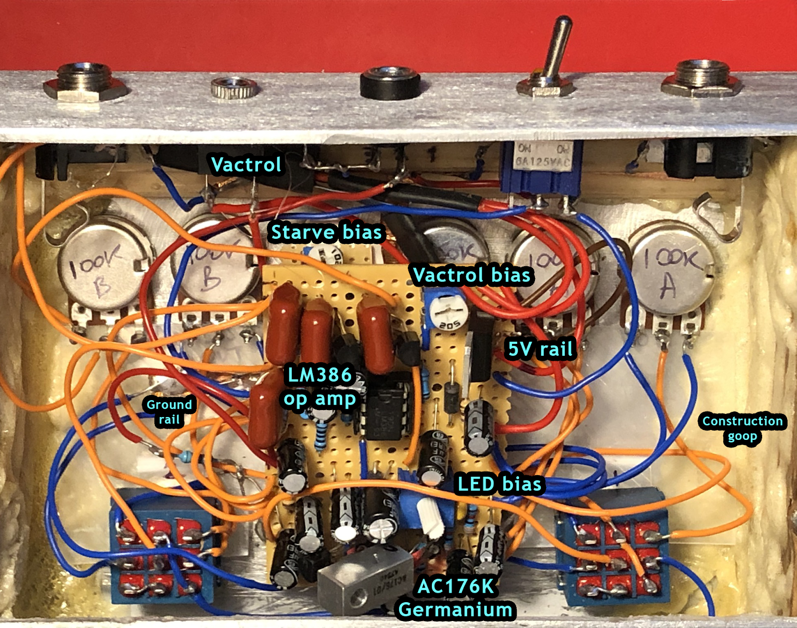
You really want to know? Ok. I won’t go into absolutely everything in here but there are some things you might get curious about, and a couple of them are actually useful for tweaking the effects.
Vactrol
CV in and Starve controls run on a 5V rail, which affects the 9V circuit of effect 2 using something called a vactrol. This is a 5V RGB LED strip taped to a group of light dependent resistors (LDRs) through which the 9V power supply runs.
These offer no resistance when it’s really bright. When the Starve control is increased (or the control voltage starts to drop) the LDRs start to resist, causing the 9V rail to sag. When fully dark the LDRs are at around 500KΩ which causes the power rail to drop to around 3V. Science!
The vactrol effect can be altered by turning the Vactrol bias. You may want to do this, I’ve tuned it to where I think is optimal but you might want a different behaviour.
The starve control range can be altered by turning the Starve bias (hidden under the main circuit). This will make the power drop out sooner if you want that.
LED bias
The LED bias is… just because I hadn’t decided what LEDs I wanted to use when I built effect 1 and I hate it when LEDs are different brightnesses, so I waited until I built effect 2 and wired its LED, then turned the LED bias to match the two front panel LEDs. Yes, I realise that’s both lazy and extravagant. Please don’t touch it.
LM386 and AC176K
Nothing to say about these other than they were hand-picked to provide the most pleasing, upsetting sound.
Construction goop
I was going to use screws to hold the sides on but I didn’t want to, OK? Let’s never talk about this again.
Blu tack
There is no blu tack in this build.
So how did you make the enclosure?
I’m glad you asked. It’s a single sheet of 3mm thick aluminium (sometimes called aluminum if you live in the Unfortunate Isles) which I wanted to bend into shape, so I built a metal brake – basically a big folding thing made from three pieces of mild steel shelving, two old gate hinges and a claw hammer.
Incidentally this claw hammer is the one left by the thief who broke into my shed. You stole all my power tools but I have your hammer, so who really won?
I then cut off the extra which I could later reattach as the base of the unit.
Next I cut a lovely piece of oak (I got from the wood wonderland, or wooderland that is Leeds Wood Recycling) into two matching ‘cheeks’ because wooden cheeks always make any device sound 20 per cent better. I finished these by routing them so they could slot nicely in to the sides of the folded piece of metal.
To finish off the aluminium I used an angle grinder to score the entire surface. I didn’t take any pictures of this because I was trying not to breathe sparks, so you’ll just have to believe me.
Then I wired it all up, which took aaaages.
Where are you now?
Well, this is rather exciting. This pedal was destined for Robbie Major of the band Benefits. I hand-delivered it when they played at the Brudenell Social Club in Leeds and he used it during the gig. Look at its little twin green LEDs glowing away on the board there.
Great gig, great band – Angry ✔️ Teesside ✔️ Noise ✔️ – and they’ve got their first album coming out in April. I’m going to pretend I definitely know my pedal features in one of their songs so I can say I’ve finally made it.
Here’s something not-a-pedal that I’ve been working on. It’s a stand with a built in amplifier and speakers for a Teenage Engineering Pocket Operator PO-20 (basically a musical calculator but so much more awesome than that description makes it sound).
The synthesiser can be slid in and out of the stand from the back. You connect the output of the Pocket Operator to the (stereo!) amp input on the back of the stand. The 3W+3W amp can be powered by USB or an internal battery.
I used the CAD drawings available on Teenage Engineering’s website to work out the exact dimensions to fit the synth in to a narrow slot cut into the face of each side.
I was worried about cutting a groove so close to the edge of plywood as I expected the layers to shear off, so I put together a very rudimentary jig, clamped my drill to the worktop and used a hobby drill cutting wheel to gradually make the slots deeper and wider. I used some drywall screws inserted over the bit to make micro-adjustments to the angle of the cutting wheel, and used pieces of cardboard in between the component and the wooden stop to alter the position of the cut. Somehow it worked!
Necessity is the mother of… look I know it’s ridiculous but it works, ok?
After sanding each part I used Birchwood Casey gun oil to treat the end grain and faces, then after 24 hours lightly sanded and applied a further coat of gun oil. I repeated this process every day for a week, then finished with a thin coat of gun wax. I think it turned out great!
The best part was putting together the speakers. I had some 30mm speakers I’d salvaged from a broken Bluetooth speaker. I created custom holders for them from 32mm PVC drain pipe, glued them in to the holders then made speaker grilles from 40mm PVC drain pipe and stretched speaker fabric over them. The custom speaker/drain pipe holder combo then fit exactly inside these grilles. This was a particularly good idea because I already had a 42mm hole cutter from when I did my kitchen plumbing a few years back 😄
It was great fun to use some of the building techniques I’ve learned from my recent wooden pedals for this project, and I am loving my ever expanding range of clamps. How did I ever live without quick release one handed clamps before this year?
My latest adventure in the world of wooden pedal building continues with the TIMBRE, powered by the Death By Audio Reverberation Machine circuit.
The pedal uses this nifty Accutronics Belton reverb module to get deep, long echoes.
It did feel a bit like cheating using this module instead of laying out on vero board but to get the same result I would have needed to build a circuit four times the size of The Colonel, which just seemed impractical.
The enclosure was made with plywood which I cut into strips and glued so the end grain shows along the front of the pedal. This included a little bit of sanding.
The pedals I’ve boxed up so far have used either Altoids tins or aluminium ‘1590B’ style boxes. While building in Altoids tins is fun they don’t allow you to fit in more than a small circuit. The 1590B enclosures present a moderate challenge to a novice like me, and I’ve enjoyed learning how to fit everything in a reasonably small space (I’m not about to try 1590As, I have no desire yet to fit everything in a tiny space just to see if I can).
Lately though I’m completing more circuits that I want to box up but finding the greatest cost is the aluminium enclosures. So, born partly of necessity and partly because I saw some amazing designs on Instagram courtesy of @glacialcreative I’ve decided to try my hand at using wood, starting with probably (as it transpires) the worst type of wood you can possibly choose for a first attempt: OSD or Oriented Strand Board.
This stuff hates not being a large flat sheet.
I’ve really challenged myself building with this, there’s loads of new problems to solve such as how to make parts of the enclosure thin enough to pass components through but still remain structurally sound, or how to cut material that’s essentially chewed up scraps of stuff and glue in a way that it doesn’t instantly disintegrate.
I’ve got some more enclosures in the works including some reclaimed kitchen worktop (!) mixed with pine (!!) and different types of plywood (!!!). Suddenly every piece of scrap wood is a potential guitar pedal material.
Watch this space! Or don’t. I mean, it’s up to you. I can’t tell you how to live your life.
When testing audio circuits I found that I was having to plug them into my big amp to test if they were working, or use my small headphone amp. This wasn’t ideal for a number of reasons. I decided to build myself a small amp with all the features I wanted to test circuits. I also wanted to be able to use it as a practice amp for use with headphones.
I found the Noisy Cricket Mk II on tagboard effects which seemed to have the features I was looking for. It has controls for volume, gain and tone, along with a ‘grit’ switch (slight overdrive) and a bass switch which flips between capacitors to allow more or less bottom end signal through. I used an LM386 op amp IC as every time I’ve used one of these in a circuit it sounds great (in my opinion, other internet opinions are available).
Noisy Cricket circuit.
As a practice amp I also wanted to include a metronome I could hear through my headphones, so I built a little astable 555 timer circuit, and attached both a white LED and a small speaker, as well as an audio output to the headphone jack.
Metronomical.
The metronome can be switched on and off, and when on I can switch between it playing out of the small internal speaker and playing out through my headphones mixed with my audio signal.
The next things I want to add are a way to play audio in from my phone to play along with, and maybe a Bluetooth receiver so I don’t need to use a cable.
Tin amp.
One of my favourite things about this amp is I can take the lid off whenever I need to mess about with the innards. As it’s primarily for testing this is ideal, as I can take readings from inside the amp if I need to.
One thing I’ve found repeatedly when testing audio circuits is that I don’t have a very good way of quickly and effectively plugging in and testing – both for power and signal path. I often find strange, intermittent faults appearing and sometimes everything stops working, which almost always turns out to be a loose test lead on a jack socket or a bad connection on the battery. Gah!
The olden days of intermittent signals. Whyyyy
I decided it was time to improve my setup to a sturdier, reliable, more permanent solution. I wanted something with fixed audio and power jacks, but with the flexibility to add and remove other parts as and when needed.
I found an old metal shelf bracket which was an ideal width and height although it was over 2 metres long. I cut a 20cm length then used an angle grinder to remove the rust and paint and take it back to bare metal. I then filed and sanded all edges to give a nice, smooth finish. I drilled holes to fit the audio and power jacks, and drilled extra holes for any potentiometers and switches I may want to add. Finally I drilled holes so I could attach the bracket to my existing breadboard setup.
Neat.
After installing the input and output audio jacks I added a DPDT (double pole, double throw) bypass switch and connected everything, adding in crocodile clip test leads from the in and out pins of the switch.
I installed a 9V power jack and wired it to a SPDT (single pole, double throw) switch, with the switched live pin attached to a crocodile clip test lead and the other pin attached to ground, so when the power is switched off the live test lead is automatically grounded. I also added a small LED (with a resistor) between these two pins so I can see at a glance when the board is powered.
Ready to test a circuit.
I wish I’d done this earlier. Having a solid setup for the in/out parts of my audio circuits has entirely removed one uncertainty from my builds – whether the basics of a good power supply and good signal path connectivity are in place. I can use it for both testing breadboard circuits and soldered vero board or PCB layouts, and the whole thing is portable so I have the freedom to leave my desk and go sit just over there instead.
Reverse angle, revealing the means of construction.
There are a couple of extra things which I’ve added or built to complete my workflow. I’ve stuck pedalboard Velcro to the side of the metal bracket so I can place my TC Electonics Ditto looper pedal on the board. This means I can pre-record a loop and play it into the board when I’m tracing audio paths and tweaking trimmer values.
Testing a Reverberation Machine build.
I’ve also built a little amp so I can take the board output straight to it and out to headphones, very exciting. I’ll go through the features of the amp in my next post.
For quite a while now I’ve been taking components from various broken electrical items that people have given me, and have a good selection of both passive components like resistors and capacitors, along with some more specialised parts that I’m planning on using in future.
One man’s trash is another man’s useful trash.
I wanted to make a fuzz effect that I found the layout for on tagboard effects which is based on the standard Bazz Fuss circuit.
I challenged myself to build it using as many salvaged parts as possible. and managed about 90%. The only new components I added were the transistors as I couldn’t find 2n3904s in anything I took apart.
It looks a bit beaten up but it works.
It sounds great! It’s a crackly, raw, high gain fuzz that makes you think your speaker is broken but in a good way. In fact, the sound is so rough around the edges that if I put it in a fancy enclosure with cool graphics on it and a huge volume knob I could sell it as boutique for £200. 😉